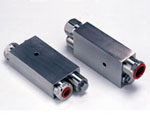
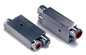
Types 14460 and 14470 integrated check/thermal relief valves
 |
|
|
The Type 14460 and 14470 check/thermal relief valves have been developed to directly replace with a single unit separate check and thermal relief valves used in wellhead control systems. The 14470 is conventionally connected (see table below) while the 14460 is manifold mounted. The principal feature of this valve is its ability to return exhausted fluid caused by thermal expansion downstream internally through the valve itself back to the supply point – thereby eliminating separate exhaust piping. 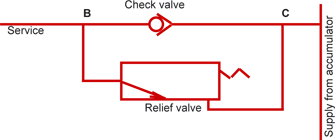
Pressure differential between B and C (see above) caused by thermal expansion downstream of B is exhausted through the relief valve back into the supply at point C. The design of the relief valve is such that variations in pressure at point C caused by the operation of adjacent |
valves or by leakage have no effect on the setting of the relief valve. Even in the event of the supply pressure falling to zero, the integrity of the relief valve will be retained. MaterialsExternal/wetted parts – 316 stainless steel
Drawing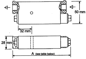 |
| Part No. | Pressure
range (bar) |
Connections | Dim A
(mm) |
Cv | Proof test pressure
(bar) |
Cracking pressure
(bar) |
Max flow
(gals/min) |
| 14460–01 | 35 – 345 | Manifold | 132 | 0.56 | 1,000 | 0.3 | 2 |
| 14460–02 | 345 – 700 | Manifold | 132 | 0.56 | 1,000 | 0.3 | 2 |
| 14470–01 | 35 – 345 | 1/4"NPT | 132 | 0.56 | 1,000 | 0.3 | 2 |
| 14470–02 | 345 – 700 | 1/4"NPT | 132 | 0.56 | 1,000 | 0.3 | 2 |
| 14470–03 | 35 – 345 | 3/8"NPT | 132 | 0.56 | 1,000 | 0.3 | 2 |
| 14470–04 | 345 – 700 | 3/8"NPT | 132 | 0.56 | 1,000 | 0.3 | 2 |
| 14470–07 | 35 – 345 | 1/2"NPT | 139 | 1.60 | 400 | 0.4 | 6 |
| 14470–08 | 345 – 700 | 1/2"NPT | 132 | 0.56 | 1,000 | 0.3 | 2 |
| 14470–10 | 345 – 700 | 9/16"MP Butech | 139 | 1.60 | 400 | 0.4 | 6 |
Test procedureEach valve is tested by Marshalsea Hydraulics and issued with a unique serial number prior to dispatch. The following describes the testing procedure. 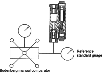
|
|